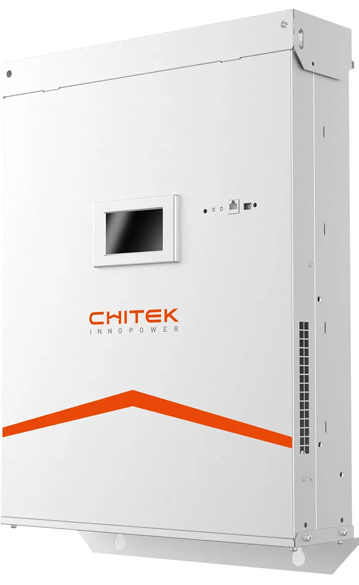
Nonlinear loads — VFDs, rectifiers, UPS, welders, switched-mode supplies — draw current in pulses and inject harmonic frequencies onto the bus. Left unchecked, that distortion overheats transformers and cables, stresses switchgear, and shortens equipment life. Two correction families exist: the passive (tuned LC) filter and the active harmonic filter (AHF). They are not interchangeable, and the right choice follows directly from the load profile.
Root Cause: Why Harmonics Appear
In a healthy LV (≤ ~1 kV) network the load current is a clean sine at the fundamental. A nonlinear load commutates in steps, producing characteristic harmonics. A 6-pulse front end, for example, generates orders n = 6k ± 1 (5th, 7th, 11th, 13th…). Uncorrected, THDi commonly lands at 8–30%, far above the IEEE 519 low-voltage ceiling of < 5% (single harmonic < 3%). As more drives and power electronics share a bus, that spectrum shifts continuously through the day.
Passive Harmonic Filter: Fixed and Tuned
A passive filter uses capacitors, reactors, and resistors to form an LC network tuned to a specific harmonic order. It works by presenting a low impedance path at the target frequency. Its strengths are simplicity and low cost — when the load is stable and the spectrum predictable.
But the limitations are structural:
- Fixed tuning — only addresses designed orders
- Resonance risk — LC resonance can amplify distortion
- No load tracking — cannot follow a bus whose harmonic content swings
Active Harmonic Filter: Dynamic and Wide-Band
A low-voltage AHF measures the load current with a CT, isolates the harmonic component, and injects an equal, opposite-phase current: ic* = iL − is(fundamental). This cancels the distortion regardless of which orders are present, covering a wide range (typically 2nd–50th) in real time with < 1 ms response. It tracks a VFD bus as drives ramp, handles mixed sources, and avoids the resonance trap entirely.
The Decision Follows the Load
Choose passive when the load is stable, harmonic orders are well known, and dynamic tracking is not required. Choose AHF when loads vary (multiple VFDs, mixed nonlinear sources), when resonance must be avoided, or when a single device must cover many orders.
On most modern LV buses — factories, water-treatment plants, data centers, commercial buildings — the load is no longer simple enough for a fixed-only approach. A hybrid (passive bulk + AHF trim) is common where a large base load coexists with a swingy harmonic source.
The Converter Core: IGBT and SiC
An AHF's performance is bounded by its power switch. A standard IGBT is rated to ~150 °C junction temperature, switching typically below 20 kHz; switching loss rises with frequency and caps tracking speed. A SiC MOSFET raises the ceiling: silicon carbide is a wide-bandgap device (3.26 eV vs. silicon's 1.12 eV), tolerates ~200 °C, switches at 2–3× the IGBT frequency, and cuts switching loss by ~50%. That means +1–3% efficiency and tighter harmonic rejection. CHITEK low-voltage AHF platforms are built on this IGBT→SiC migration path.
Conclusion
Passive filters earn their place on stable, predictable loads; active filters earn theirs on dynamic, nonlinear ones. The wrong choice — a fixed filter on a swingy VFD bus — risks resonance and mistracking. Measure the real bus, then match the device to the load.
Which filter technology fits your bus? Contact CHITEK for a harmonic study and a data-driven recommendation.