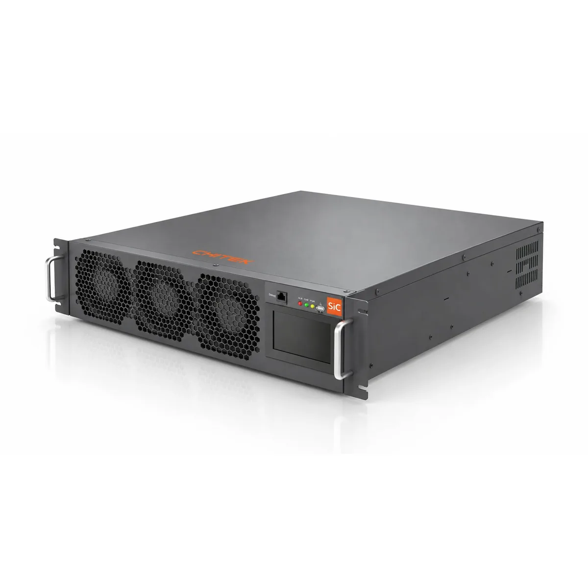
Power Quality Solutions for Industrial Manufacturing
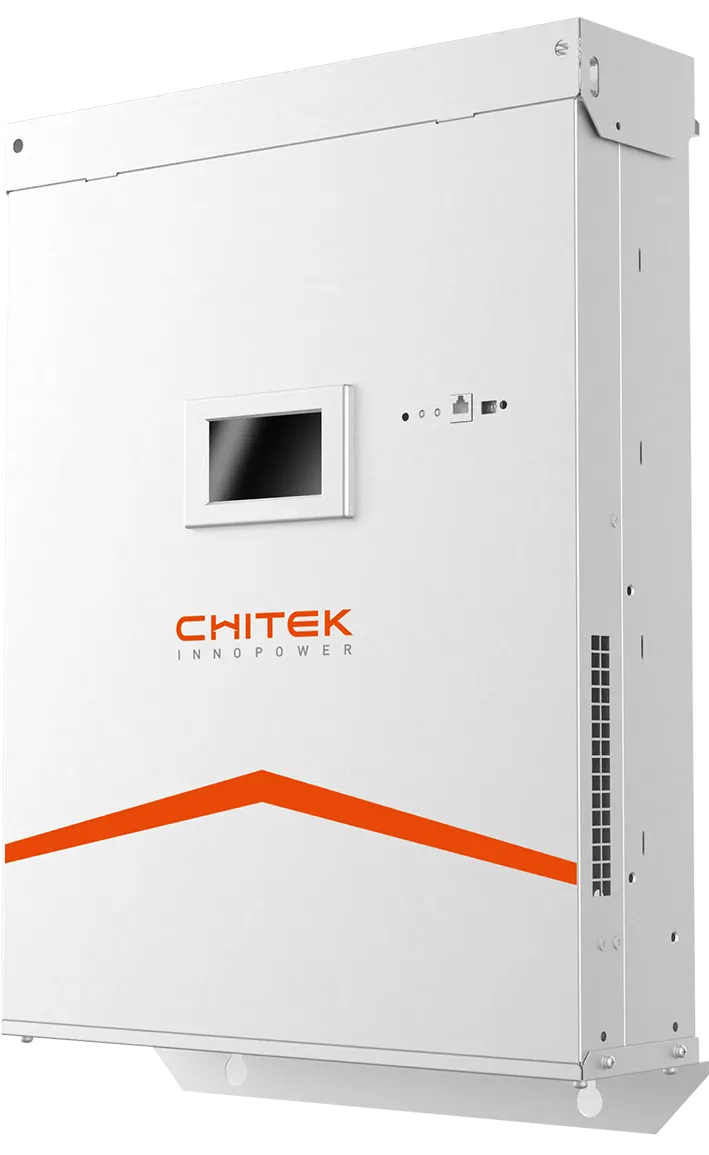
CHITEK conditions harmonic and reactive problems on industrial plant feeders using active harmonic filters (AHF) and static var generators (SVG). The usual triggers are VFD banks, welding equipment and induction furnaces. Sizing follows a measured harmonic spectrum at the point of common coupling, not the transformer rating alone.
Welding banks, induction furnaces, CNC servo drives and large VFD installations all inject harmonic current back into the plant feeder. The result is transformer overheating, recurring capacitor failures and unstable process equipment. CHITEK active harmonic filters (AHF) and static var generators (SVG) are installed at the transformer or at the feeder to bring distortion back inside the plant limits.
Reviewed by the CHITEK power quality engineering team · Last updated
AHF or SVG for a manufacturing plant?
Most industrial sites start by identifying which of the two problems is dominant. Distortion and reactive demand are measured separately in the survey, and either can be the binding constraint.
Aspect
AHF (Active Harmonic Filter)
SVG (Static Var Generator)
What it does
Injects a compensating current that cancels the harmonic current drawn by non-linear loads.
Supplies or absorbs reactive power continuously to hold power factor and support voltage.
Primary target
Current distortion (THDi) and harmonic spectrum at the point of common coupling.
Power factor, voltage fluctuation and reactive demand across the load cycle.
Low or swinging power factor, voltage sag and rise, weak or long feeders, EV load steps.
Behaviour at light load
Compensation scales with the measured harmonic current, so output falls as load falls.
Holds output as required to reach the target power factor even at near-zero active load.
Use in this sector
Feeder-level harmonic correction at the transformer or at the main incomer feeding VFD and furnace loads.
Reactive support where power factor penalties apply or where furnace switching causes voltage fluctuation.
Ratings are set from the survey. Where a plant runs both VFD banks and furnaces, the two devices are normally combined rather than sized as alternatives.
Data Error — ATE power supply ripple rejection degraded, false DUT rejection, yield reporting error
Neutral Overheat — High zero-seq current in test floor PDU, N-line temp > 90°C, fire risk
Industrial case studies
Each case below is written up the same way: what the site was, what the survey measured before anything
was specified, what was installed, and what the acceptance test showed afterwards. Projects marked
Typical Configuration are illustrative — sizing
for those always starts from a site survey rather than from the table.
Electronics Manufacturing
Harmonic Retrofit on a 550 A Plant Feeder — Electronics Manufacturer, Guangdong
Current distortion 20.06% → 2.58% on a VFD / compressor / pump feeder
Background
Feeder TM8 at an electronics manufacturing plant, supplying variable-frequency drives, air compressors and cooling water pumps. The circuit already carried 390 kvar of capacitor compensation within a 780 kvar installed bank, and ran between 800 A and 1,000 A at a system power factor of 0.92.
What we measured
Running current 800–1,000 A on feeder TM8
Current distortion 20.06% before the retrofit
System displacement power factor 0.92
390 kvar of capacitor compensation on the circuit, 780 kvar installed
Equipment installed
AHF-550A × 1 unitsActive Harmonic FilterHarmonic compensation on feeder TM8
Project overview
Feeder TM8 supplies VFDs, air compressors and cooling water pumps, with 390 kvar of capacitor compensation on the circuit (780 kvar installed). Running current 800–1,000 A, system displacement power factor 0.92 before retrofit.
Before / After
Distortion 20.06% → 2.58%
Key results
Current distortion 20.06% → 2.58%
Harmonic amplification and system resonance avoided
Accepted on test against GB/T 14549
Scope and limitations
Results are reported for the TM8 feeder only. Other feeders at the same plant were not part of this contract and are not covered by the figures.
Precision Optics Manufacturing
Centralised Harmonic Mitigation Across Five 2,000 kVA Transformers — Optical Component Manufacturer, Dongguan
Harmonic current 146.22 A → 30.96 A (TR4) and 124.71 A → 43.99 A (TR5)
Background
A ground-floor LV switchroom with five 2,000 kVA transformers at roughly 90% load, each feeding variable-frequency drives, optical production machinery and motors, with three capacitor-reactor cabinets totalling 720 kvar.
GB/T 14549 limits for these orders: 62 / 62 / 44 A
Equipment installed
AHF-500A × 5 unitsActive Harmonic FilterOne cabinet per 2,000 kVA transformer in the LV switchroom
Project overview
Ground-floor LV switchroom with 5 × 2,000 kVA transformers, each paired with a 500 A active filter cabinet. Load is VFDs, optical production machines and motors, with three capacitor-reactor cabinets totalling 720 kvar. Measured at 90% load factor.
Before / After
TR4 146.22 A → 30.96 A · TR5 124.71 A → 43.99 A
Key results
Distortion TR4 5.39% → 1.38%, TR5 4.68% → 1.67%
3rd harmonic TR4 122.52 A → 12.69 A, TR5 100.04 A → 17.89 A
Every monitored order inside GB/T 14549 limits (62 / 62 / 44 A for 3rd / 5th / 7th)
Accepted on test — result described as ideal in the commissioning report
Scope and limitations
Published results cover transformers TR4 and TR5 only; the remaining three transformers are not reported here. Filter module availability during the reporting window is outside the scope of this write-up.
Metals & Induction Heating
Resonance-Free Harmonic Control on an Induction Melting Furnace
Start-up resonance, grid voltage notches and commutation upset — all three solved
Background
A metal melting shop running an induction furnace. The current waveform is close to a square wave, so harmonic content is high; repeated grid voltage notches at start-up stress any active filter on the feeder.
Equipment installed
AHF × 1 unitsActive Harmonic FilterFurnace feeder, with revised output inductor and capacitor parameters
Project overview
Induction furnaces are a hard load for any active filter. The current waveform is close to a square wave, so harmonic content is high and resonance comes easily. Repetitive grid voltage notches at start-up stress the filter. And on switch-on the output inductor resonates with the filter capacitor, tripping output-current protection — which in turn upsets furnace commutation.
Why there is no before / after here
Measured before/after values are not published for this project. What follows is the engineering problem and how it was solved.
Key results
Output inductor and filter capacitor re-parameterised to break the switch-on resonance
Start-up and load-step output-current alarms removed by a control software update
Furnace commutation restored to normal operation
Distortion brought inside the national grid requirement without triggering resonance
Scope and limitations
No measured before-and-after figures are published for this project, so the entry describes the engineering problem and the remedy rather than a result table. Treat it as a capability note, not a performance claim.
Frequently asked questions
What causes harmonics in a manufacturing plant?
Non-linear loads: rectifiers in VFDs and servo drives, arc welders, induction melting furnaces and DC power supplies. They draw current in short pulses rather than as a sine wave, and those pulses appear as harmonic current on the feeder.
Can an active harmonic filter run alongside an existing capacitor bank?
Yes, but where the filter CTs sample matters. If the CTs are on the grid side and the connection point sits downstream of a pure capacitor bank, the filter can excite LC resonance. Use selective filtering orders with anti-resonance control, or move CT sampling to the load side.
Do I need an AHF, an SVG, or both?
An AHF cancels harmonic current. An SVG supplies or absorbs reactive power and holds power factor. If the problem is distortion, start with AHF. If it is low power factor or voltage fluctuation, start with SVG. Plants running both VFD banks and furnaces often need both.
How is filter capacity sized?
From a power quality survey at the point of common coupling: measure the harmonic spectrum, the reactive profile and the load cycle. Sizing from transformer kVA alone is the most common reason an installation ends up undersized.
Every project on this page started with a measured survey. Send us your single-line diagram and load list and we
will tell you what we would measure first.