Power Quality Solutions for Renewable Energy & Storage
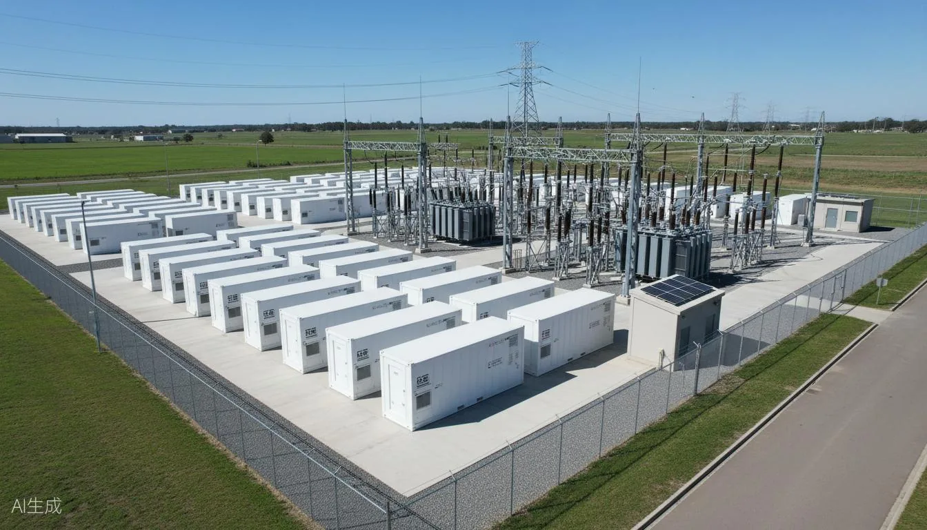
CHITEK controls harmonic interleaving, flicker and reactive swing at PV, wind and battery-storage interconnect points using combined SVG and AHF equipment. Several inverters switching on one bus interleave their emissions, and charge-to-discharge transitions produce a reactive step. Compliance is assessed where the grid operator measures it: the point of common coupling.
PV inverters, full-power wind converters and battery PCS units all switch at high frequency. Several units on one interconnect point interleave their harmonics, and the charge and discharge transition produces a reactive step and a flicker event. The compliance question is what the grid operator measures at the point of common coupling.
Reviewed by the CHITEK power quality engineering team · Last updated
AHF or SVG at an interconnect point?
At a PV, wind or storage interconnect the two problems arrive together, because the same inverters produce both switching harmonics and reactive swing.
Aspect
AHF (Active Harmonic Filter)
SVG (Static Var Generator)
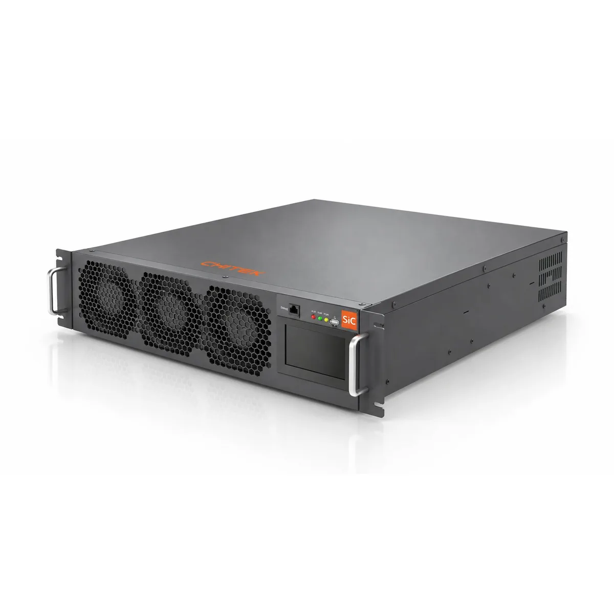
What it does
Injects a compensating current that cancels the harmonic current drawn by non-linear loads.
Supplies or absorbs reactive power continuously to hold power factor and support voltage.
Primary target
Current distortion (THDi) and harmonic spectrum at the point of common coupling.
Power factor, voltage fluctuation and reactive demand across the load cycle.
Each case below is written up the same way: what the site was, what the survey measured before anything
was specified, what was installed, and what the acceptance test showed afterwards. Projects marked
Typical Configuration are illustrative — sizing
for those always starts from a site survey rather than from the table.
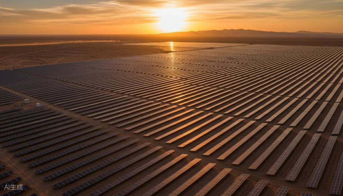
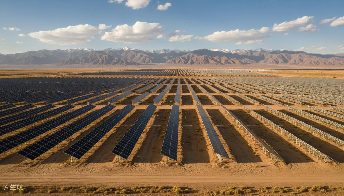
Typical Configuration · Solar PV
Typical Configuration — Solar PV Plant
Illustrative configuration — sizing starts from a site power-quality survey
Background
An illustrative arrangement for a utility-scale or distributed PV plant: SVG at the step-up bus, AHF on the inverter AC feeders.
Equipment installed
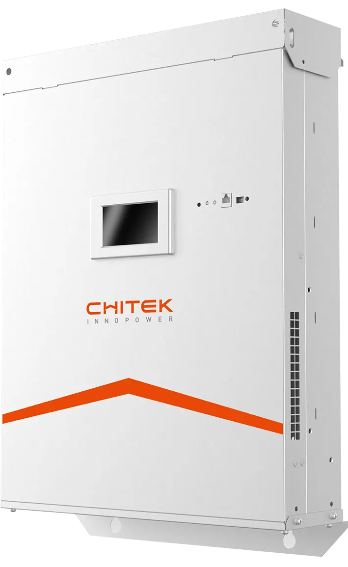
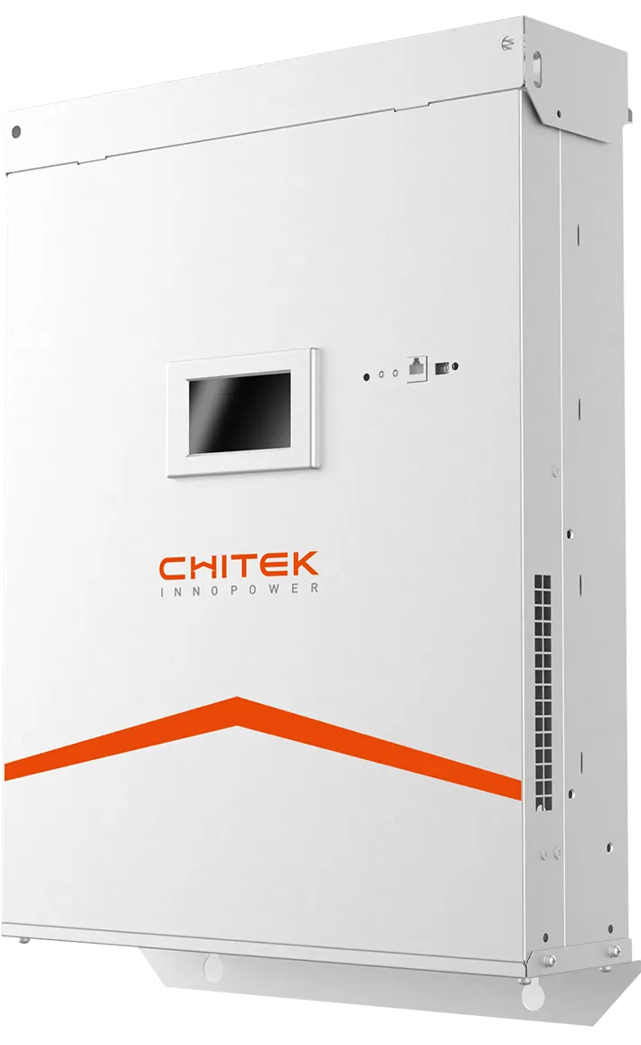
SVG × 2 unitsStatic Var GeneratorStep-up bus reactive support
AHF-200A × 4 unitsActive Harmonic FilterInverter AC feeder harmonic filtering
Project overview
For utility-scale and distributed PV, the usual arrangement is an SVG at the step-up bus plus AHF on the inverter AC feeders. Multi-inverter resonance and cloud-edge reactive swings are the two failure modes — both need a measurement campaign before ratings are fixed.
Why there is no before / after here
Illustrative configuration — not a specific delivered project. Reference projects in this sector are available on request.
Key results
Resonance scan across the collector network before sizing
Reactive envelope checked against the AVC dispatch setpoint
Ask us for reference projects in solar PV
Typical Configuration · Wind Farm
Typical Configuration — Wind Farm
Illustrative configuration — sizing starts from a site power-quality survey
Background
An illustrative arrangement for an onshore or offshore wind farm, where full-power converters and collector cable capacitance interact near the 7th harmonic.
Equipment installed
SVG-690V × 2 unitsStatic Var GeneratorCollector bus reactive support
For full-power-converter turbines, the usual arrangement is an SVG at the collector bus plus AHF on the collector feeders. Cable capacitance against transformer inductance often puts a parallel resonance point near the 7th harmonic, so the collector system is modelled before anything is ordered.
Why there is no before / after here
Illustrative configuration — not a specific delivered project. Reference projects in this sector are available on request.
Key results
Collector resonance point modelled against cable capacitance
Gust-driven reactive swing measured over a full season if possible
Ask us for reference projects in wind
Typical Configuration · Energy Storage
Typical Configuration — Battery Energy Storage
Illustrative configuration — sizing starts from a site power-quality survey
Background
An illustrative arrangement for a grid-side, user-side or source-side battery installation, where PCS units interleave harmonics and standby mode drives power factor down.
Equipment installed
SVG + AHF × 2 unitsAHF + SVG combined unitPCS AC bus power quality conditioning
For grid-side and user-side storage, the usual arrangement is an SVG + AHF combination on the PCS AC bus. Charge/discharge transitions are the stress case: multi-PCS harmonic interleaving plus a flicker step at the mode change, both measured at the point of common coupling.
Why there is no before / after here
Illustrative configuration — not a specific delivered project. Reference projects in this sector are available on request.
Key results
Charge/discharge transition measured, not assumed
Flicker at the interconnect point checked against the grid agreement
Ask us for reference projects in energy storage
Frequently asked questions
What power quality problems appear at a PV or storage interconnect point?
Wideband harmonic emissions from many inverters switching together, reactive swing as irradiance or state of charge changes, and voltage flicker at the interconnect. Multi-inverter LCL filter interaction can also produce resonance.
Why does power factor drop at low output?
Inverters and PCS units are rated for active power. At low output their reactive capability is a smaller share of what the plant needs, and cable and transformer capacitance can push the measured power factor leading or lagging depending on the hour.
Can one device handle both harmonics and reactive power?
A combined SVG plus AHF arrangement is the usual answer. The SVG holds power factor and voltage, the AHF removes switching harmonics, and the ratings are split according to what the survey finds.
What does grid compliance depend on?
The grid agreement and the local standard, measured at the point of common coupling. Emission limits, flicker and reactive capability are all assessed there, so the survey should be taken at that point rather than at the inverter terminals.
Every project on this page started with a measured survey. Send us your single-line diagram and load list and we
will tell you what we would measure first.