Power Quality Solutions for Rail Transit & EV Charging
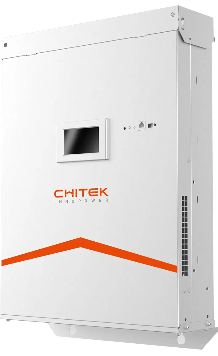
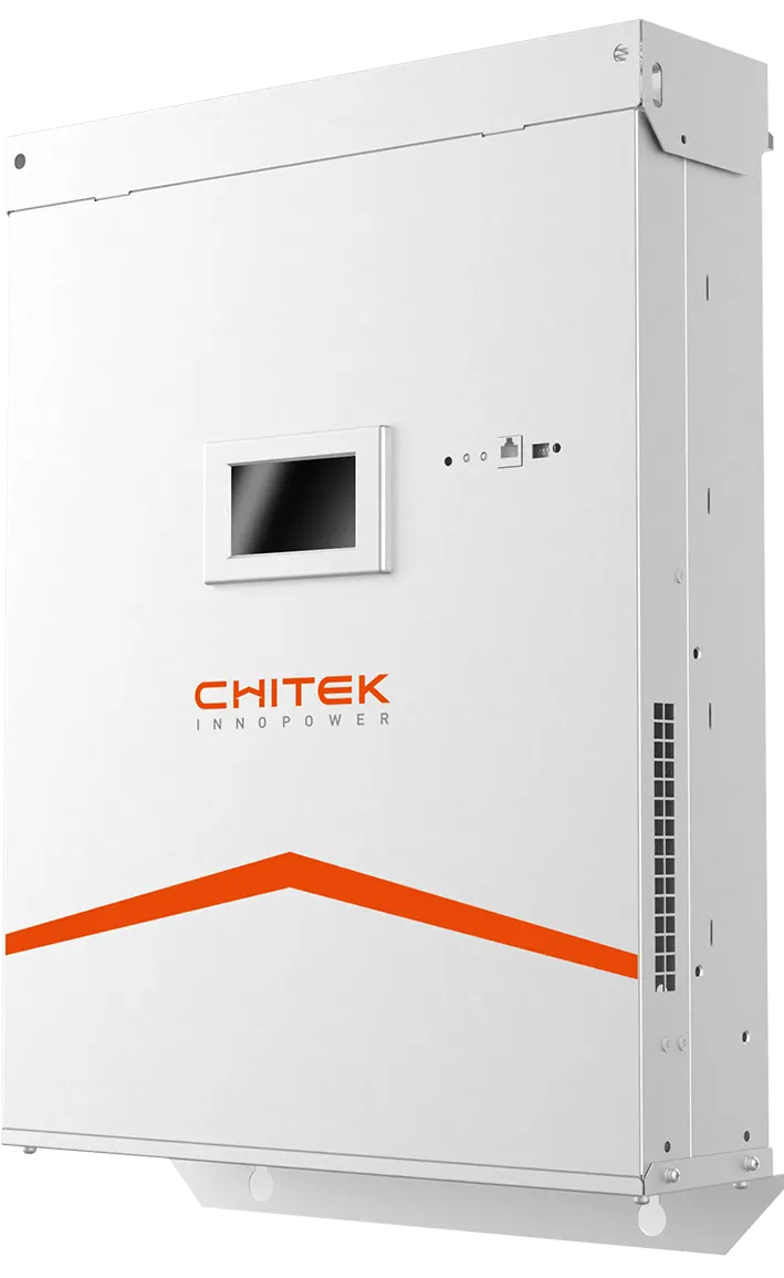
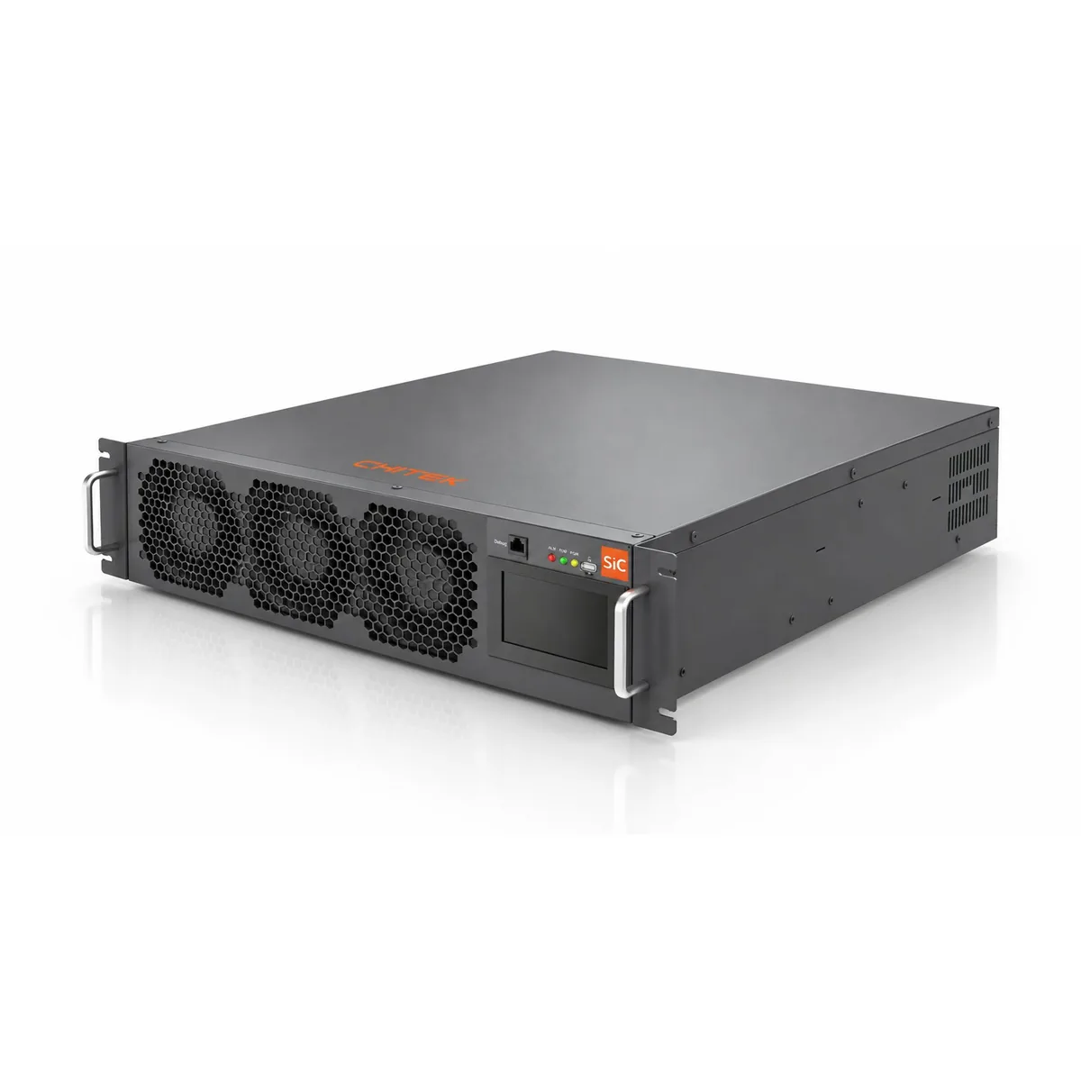
CHITEK supplies AHF and SVG for traction substations, rail feeders and EV charging sites, where large single-phase and pulsed loads inject harmonics and negative-sequence current. Traction rectifiers and DC fast chargers also pull power factor down at peak. Ratings follow a survey of harmonic spectrum, unbalance and reactive profile at the supply point.
Traction rectifiers, 27.5 kV single-phase feeds and DC fast chargers are all large single-phase or pulsed loads. They inject harmonics and negative-sequence current into the supply and pull power factor down at the charging peak. CHITEK supplies AHF for the harmonic feeders and SVG for reactive support at the transformer.
Reviewed by the CHITEK power quality engineering team · Last updated
AHF or SVG for traction and charging?
Traction and charging loads are pulsed and often single-phase, so unbalance and reactive step appear alongside distortion.
Aspect
AHF (Active Harmonic Filter)
SVG (Static Var Generator)
What it does
Injects a compensating current that cancels the harmonic current drawn by non-linear loads.
Supplies or absorbs reactive power continuously to hold power factor and support voltage.
Primary target
Current distortion (THDi) and harmonic spectrum at the point of common coupling.
Power factor, voltage fluctuation and reactive demand across the load cycle.
Life Shorten — Cyclic thermal stress from peaking load, insulation aging 5x faster, expected life < 3 years
3-phase Uneven — Single-phase AC chargers dominate, zero-seq current > 40%, N-line replacement every 2 years
Rail Transit case studies
Each case below is written up the same way: what the site was, what the survey measured before anything
was specified, what was installed, and what the acceptance test showed afterwards. Projects marked
Typical Configuration are illustrative — sizing
for those always starts from a site survey rather than from the table.
EV Charging
Power Factor Correction at an EV Charging Site — 100 kvar SVG on Each Transformer
Power factor held at target in both standby and charging; payback inside two years
Background
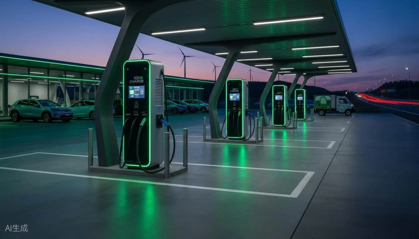
A charging site on two transformers, 2,500 kVA and 2,000 kVA. Measured at the LV incoming panel the site sat at 0.1–0.2 capacitive power factor, because chargers draw almost no active power on standby while their rectifiers continue to exchange reactive power.
Equipment installed
SVG-100kvar × 2 unitsStatic Var GeneratorOne per transformer; constant-reactive mode carries the standby condition
Project overview
Charging site on two transformers (2,500 kVA and 2,000 kVA). Measured at the LV incoming panel, the site ran at 0.1–0.2 capacitive power factor because chargers draw almost no active power on standby while their rectifiers still exchange reactive power — a conventional capacitor bank cannot follow that. One existing capacitor cabinet was stripped and reused to house the SVG modules.
Before / After
Power factor 0.1–0.2 capacitive → target value held in standby and under load
Key results
Power factor at target in both standby and charging states
About 76,000 CNY saved per year across the two transformers
Line losses reduced and end-of-line voltage improved
Payback inside two years; existing capacitor cabinet reused instead of a new one
Needs 0.2-class or better CTs — standby current is very low
Scope and limitations
The savings figure follows from the site's own tariff and load profile and is not transferable to another site. CT accuracy of 0.2 class or better is a prerequisite, not an option.
Typical Configuration · Metro & LRT
Typical Configuration — Metro & Light Rail
Illustrative configuration — sizing starts from a site power-quality survey
Background
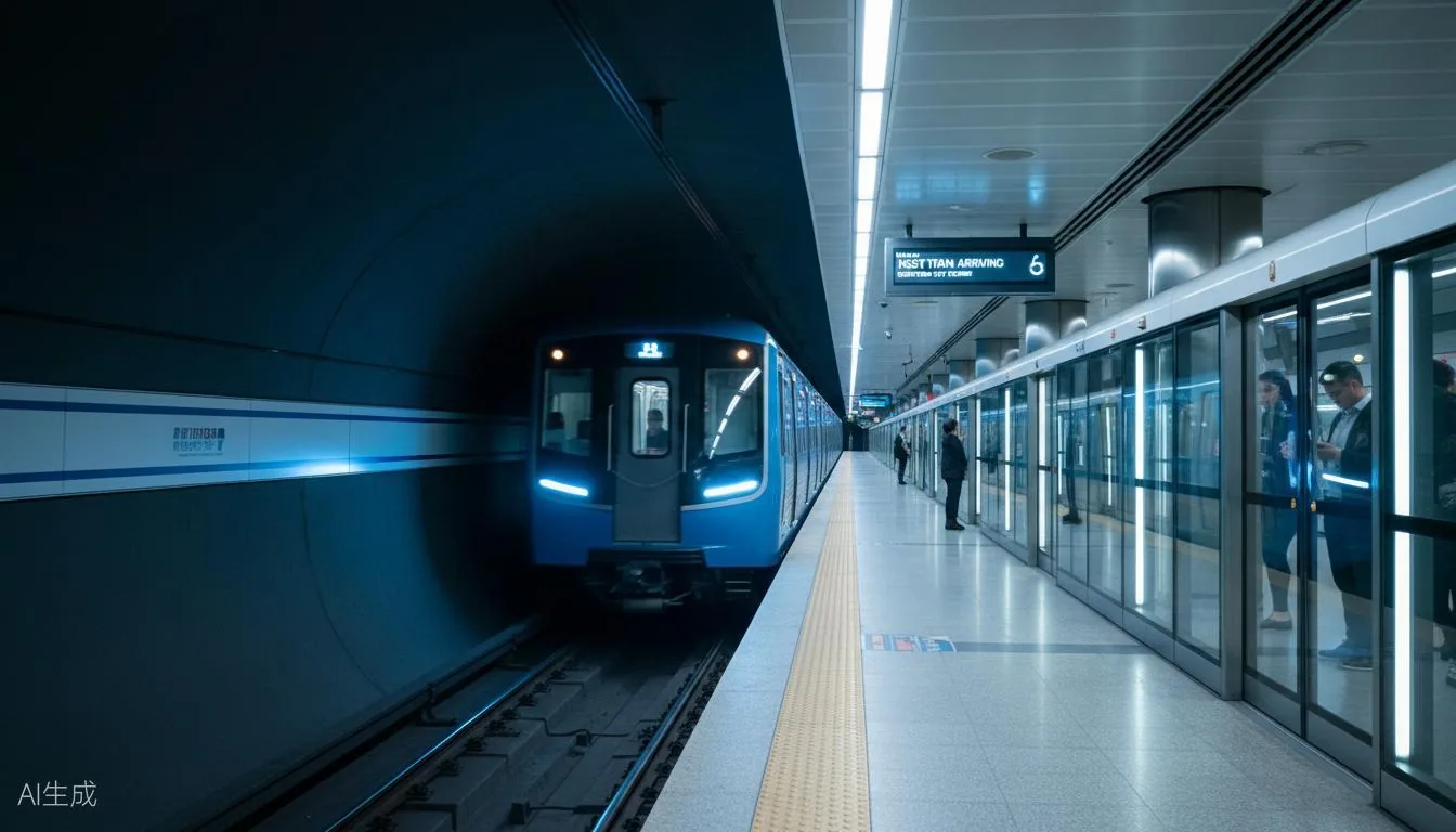
An illustrative arrangement for a metro or light-rail network: SVG on the ring bus for reactive and voltage support, AHF at the traction substation rectifier.
Equipment installed
SVG-300A × 3 unitsStatic Var GeneratorRing bus reactive compensation
For metro and light-rail networks, the usual arrangement is an SVG on the ring bus plus AHF at the traction substation rectifier. Characteristic harmonics from the rectifier and the voltage rise from regenerative braking are the two things that have to be measured before anything is sized.
Why there is no before / after here
Illustrative configuration — not a specific delivered project. Reference projects in this sector are available on request.
Key results
Rectifier harmonic spectrum measured at the substation before sizing
Regenerative voltage rise checked against inverter DC-link limits
Ask us for reference projects in metro and light rail
Typical Configuration · High-speed Rail
Typical Configuration — High-speed Rail Traction
Illustrative configuration — sizing starts from a site power-quality survey
Background
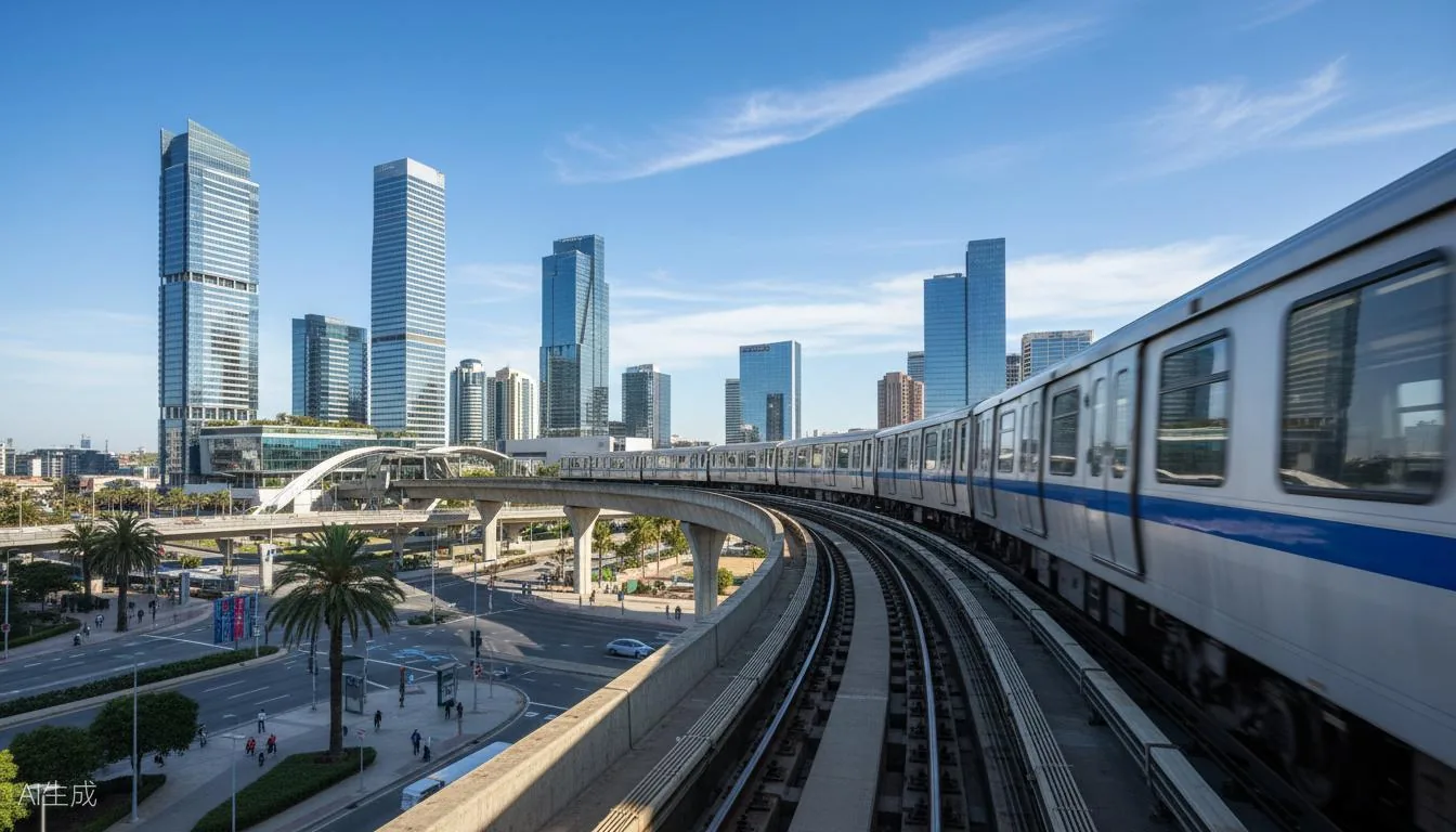
An illustrative arrangement for a 27.5 kV traction substation, where single-phase load produces negative-sequence current and the AT feed suffers end-of-line voltage drop.
Equipment installed
SVG-27.5kV × 2 unitsStatic Var GeneratorTraction bus reactive and balancing
For V/V-connected traction substations feeding single-phase catenary, the usual arrangement is an SVG on the traction bus plus AHF on the station feeder. Negative sequence at the upstream PCC is the binding constraint, so it drives the rating — not the harmonic level on its own.
Why there is no before / after here
Illustrative configuration — not a specific delivered project. Reference projects in this sector are available on request.
Key results
Negative sequence at the upstream PCC measured first — it sets the rating
Targets GB/T 15543 unbalance limits
Ask us for reference projects in rail traction
Frequently asked questions
Why is negative-sequence current a problem for traction supply?
A single-phase traction load connected between two phases of a three-phase system produces negative-sequence current. That heats three-phase machines on the same network and can push unbalance past the grid limit.
Do EV charging sites need AHF or SVG?
Mostly SVG. The main issue at a charging site is reactive demand and power factor across the standby and charging states, plus the load step when several vehicles start together. AHF is added when charger harmonics also have to be held inside limits.
Can regenerative braking raise the supply voltage?
Yes. Energy fed back during braking raises voltage on the DC and AC side, and converters may trip on overvoltage. Handling it belongs to the traction power study rather than to a filter on its own.
How long does the investment take to pay back?
For a charging site the payback is driven mainly by avoided power factor penalties. It depends on the local tariff and the site load profile, so the number comes from your tariff rather than from a product sheet.
Every project on this page started with a measured survey. Send us your single-line diagram and load list and we
will tell you what we would measure first.