Power Quality Solutions for Transmission & Distribution
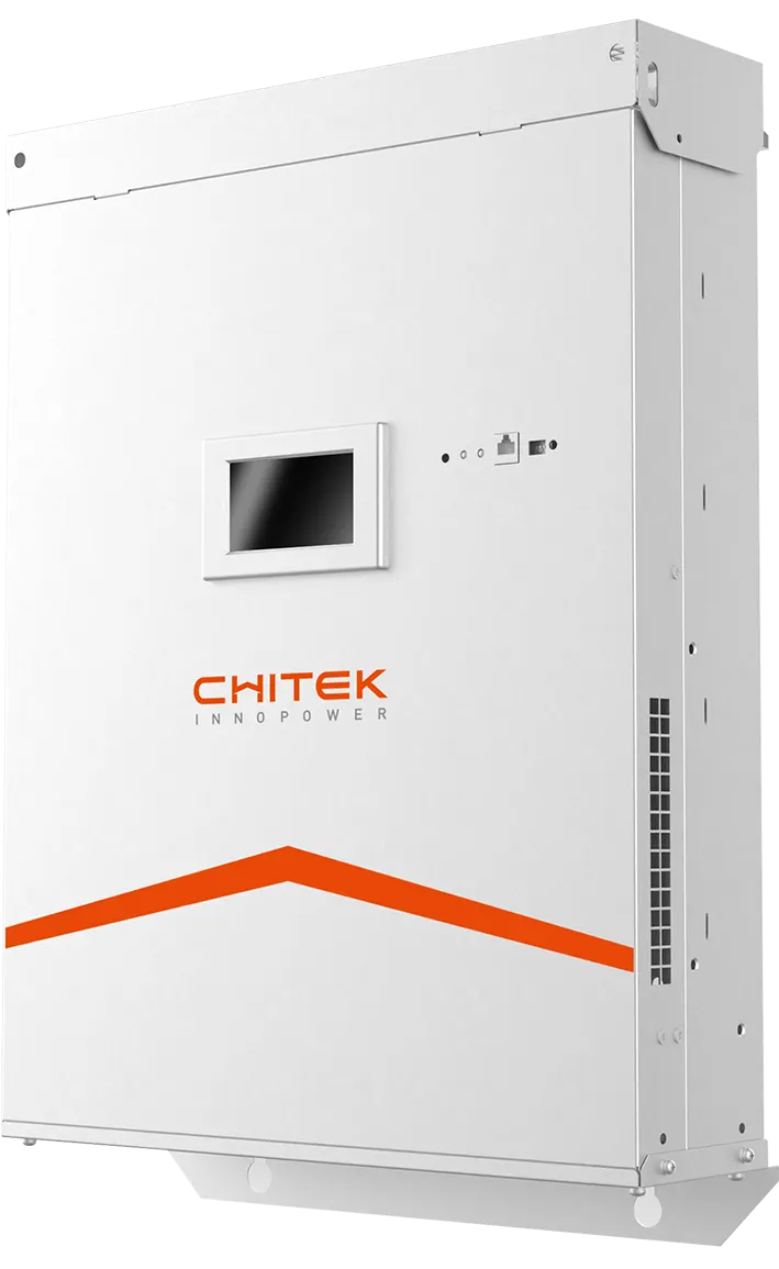
CHITEK provides reactive support and harmonic control for utility and distribution networks using SVG for voltage and power factor, and AHF where industrial or traction loads inject harmonics. Distributed generation, long feeders and EV clusters each stress the network differently, so ratings are set from measurements at the point of common coupling.
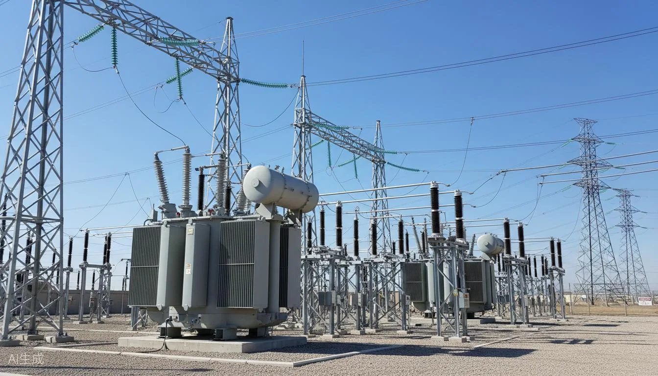
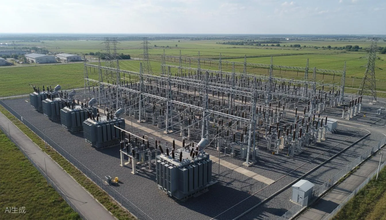
Transmission and distribution networks carry the combined effect of everything downstream: industrial harmonics, traction unbalance, distributed generation and long-line reactive loss. The usual CHITEK arrangement is an SVG on the busbar for voltage and reactive support, with AHF on the feeders that carry the worst harmonic load.
Reviewed by the CHITEK power quality engineering team · Last updated
AHF or SVG on a distribution network?
On utility and distribution networks the two devices address different network constraints, and both are normally specified together at the planning stage.
Aspect
AHF (Active Harmonic Filter)
SVG (Static Var Generator)
What it does
Injects a compensating current that cancels the harmonic current drawn by non-linear loads.
Supplies or absorbs reactive power continuously to hold power factor and support voltage.
Primary target
Current distortion (THDi) and harmonic spectrum at the point of common coupling.
Power factor, voltage fluctuation and reactive demand across the load cycle.
Cycle Life Loss — Excess reactive current heats battery PCS, accelerated IGBT aging, warranty void risk
Grid Switching
Voltage sag during island/grid transition
>20%
Sag Depth
Load Trip — STS transfer > 4ms causes contactor dropout, critical load UPS transfer to battery
Diesel Start Fail — Sag during generator start sequence, AVR excitation collapse, black-start failure
Power Grid case studies
Each case below is written up the same way: what the site was, what the survey measured before anything
was specified, what was installed, and what the acceptance test showed afterwards. Projects marked
Typical Configuration are illustrative — sizing
for those always starts from a site survey rather than from the table.
Typical Configuration · Power Grid
Typical Configuration — Transmission & Distribution Reactive Support
Illustrative configuration — sizing starts from a site power-quality survey
Background
An illustrative arrangement for a substation or rural feeder upgrade: SVG on the 35 kV / 10 kV busbar for reactive and voltage support, with AHF placed only on the feeders carrying the worst harmonic load.
Equipment installed
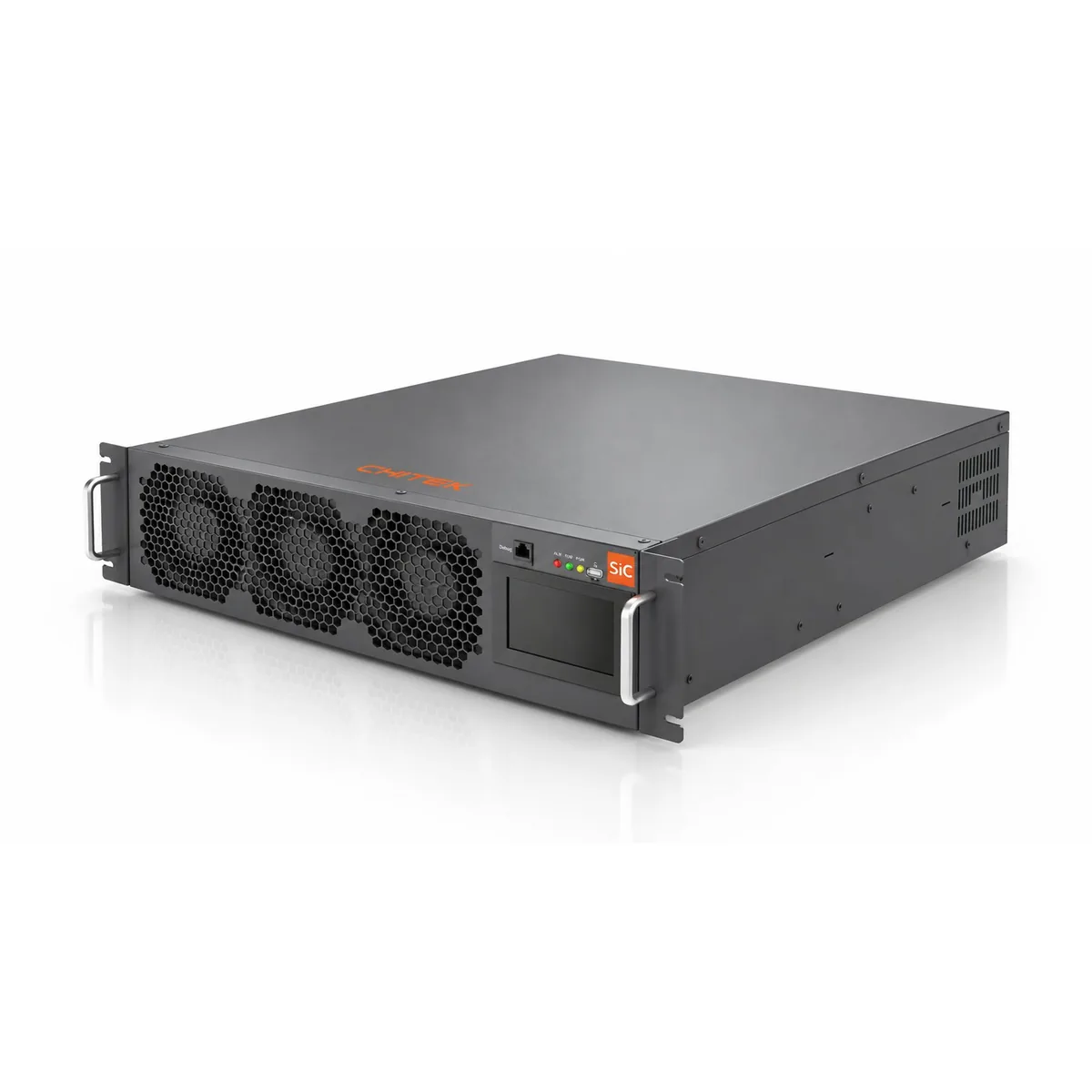
SVG × 2 unitsStatic Var GeneratorBusbar reactive voltage support
For substations serving a mix of industrial and traction load, the usual arrangement is an SVG on the busbar for reactive voltage support plus AHF on the critical feeders for harmonics. Ratings are set by a survey, not by a template — the quantities below are a starting point only.
Why there is no before / after here
Illustrative configuration — not a specific delivered project. Reference projects in this sector are available on request.
Key results
Sized from a measured harmonic spectrum and reactive profile
Designed to GB/T 14549 limits at the point of common coupling
Ask us for reference projects in transmission and distribution
Typical Configuration · Urban Distribution
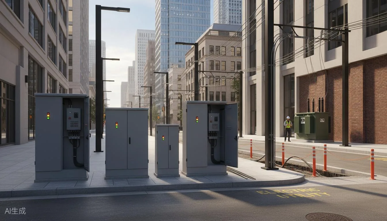
Typical Configuration — Urban Distribution Network
Illustrative configuration — sizing starts from a site power-quality survey
Background
An illustrative arrangement for a city-centre or development-zone network carrying EV clusters, commercial single-phase load and cable-fed residential areas.
Equipment installed
SPC-150A × 4 unitsStatic Power CompensatorCharging bay 3-phase balancing
SVG × 2 unitsStatic Var GeneratorFeeder reactive compensation
Project overview
For city-centre 10 kV networks carrying EV fast-charging clusters plus mixed commercial and residential load, the usual arrangement is a phase-balancing device at the charging feeder and an SVG on the feeder for reactive support. Underground cable capacitance at light load has to be checked before sizing, or the SVG will fight it.
Why there is no before / after here
Illustrative configuration — not a specific delivered project. Reference projects in this sector are available on request.
Key results
Sizing validated against a light-load capacitive check
Targets GB/T 15543 unbalance limits at every charging station
Ask us for reference projects in urban distribution
Typical Configuration · Microgrid
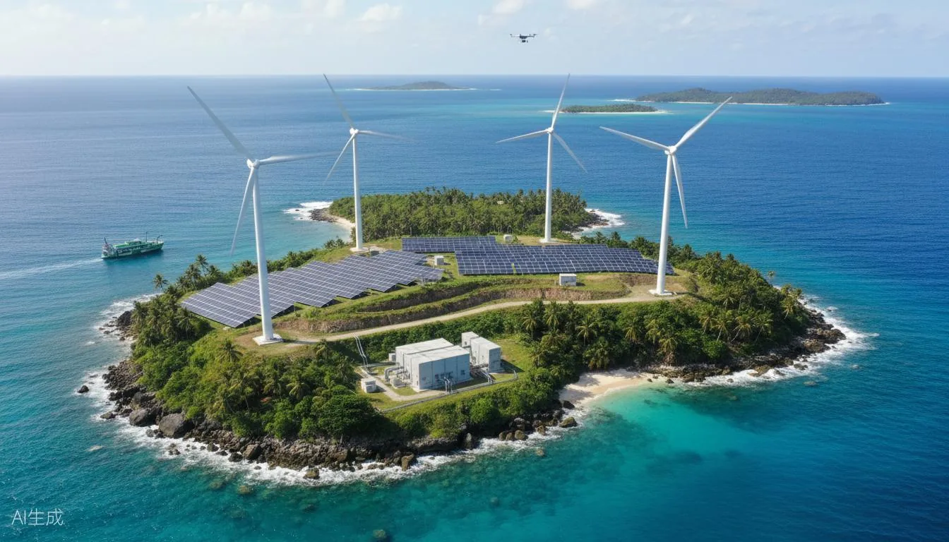
Typical Configuration — Microgrid & CCHP
Illustrative configuration — sizing starts from a site power-quality survey
Background
An illustrative arrangement for a campus, island or remote microgrid combining PV, battery storage and diesel back-up on one point of common coupling.
SPC-100A × 1 unitsStatic Power CompensatorLoad balance across phases
Project overview
For island and campus microgrids combining PV, wind, storage and diesel, the usual arrangement is an SVG + AHF combination at the point of common coupling plus a balancing device across phases. Multi-inverter harmonic superposition and the island/grid transfer sag both have to be measured before ratings are fixed.
Why there is no before / after here
Illustrative configuration — not a specific delivered project. Reference projects in this sector are available on request.
Key results
Harmonic study across all inverter types before sizing
Island/grid transfer behaviour verified by measurement
Ask us for reference projects in microgrids
Frequently asked questions
Where do SVG and AHF go in a substation?
SVG on the busbar for reactive voltage support, AHF on the specific feeders with the highest harmonic load. Treating an entire station for harmonics is rarely economic.
What causes end-of-line voltage collapse on rural feeders?
Reactive loss over a long line. As current rises, both the resistive and the reactive drop grow, and the voltage at the far end falls out of the usable band. Reactive support near the load end is usually more effective than raising the source voltage.
Does distributed generation change the power quality picture?
Yes. Reverse power flow raises voltage at the connection point and inverters add switching harmonics. Protection coordination and tap changer behaviour both need rechecking when DG capacity grows.
Can an underground cable network be over-compensated?
Yes. Cable capacitance generates reactive power at light load and can push the measured power factor leading, which raises voltage and stresses insulation. It also creates a parallel resonance risk with the transformer inductance.
Every project on this page started with a measured survey. Send us your single-line diagram and load list and we
will tell you what we would measure first.