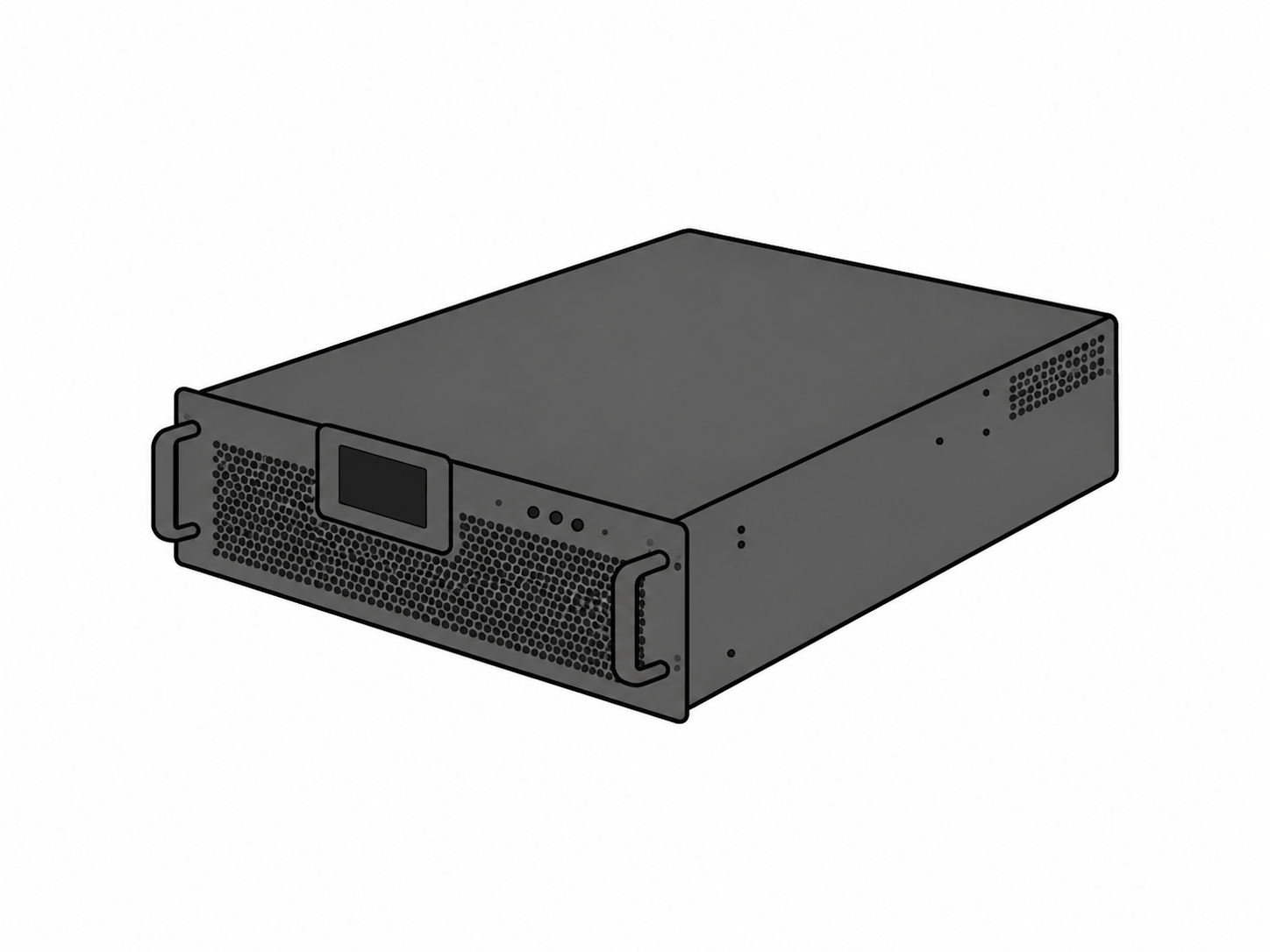
A three-phase system is balanced when all phase voltages are equal in magnitude and 120° apart. In real plants — large single-phase loads, arc furnaces, rectifiers, uneven feeder impedances — that ideal breaks. The result is negative-sequence current that heats motors, derates transformers, and distorts the waveform. This article covers the causes, the cost, and why a low-voltage (LV) SVG + AHF is the dynamic correction.
How Unbalance Is Quantified
The standard metric (NEMA MG-1 / IEC 60034) expresses voltage unbalance as a percentage:
V_unbalance% = (maximum deviation from average phase voltage) / (average phase voltage) × 100%
Systems are typically classified as unbalanced above about 1–3%. IEC 61000-3-13 outlines the acceptable limits.
Major Causes
- Uneven load distribution — unequal loading across the three phases.
- Large single-phase loads — heaters, welders, and EV chargers on one phase draw excessive current.
- Line asymmetry — unequal impedance or a non-symmetric line configuration, worse on long feeders.
- Faulty equipment — damaged transformers or poor connections.
- Distributed generation — asymmetrical PV or ESS injection can unbalance a weak bus.
What It Costs
- Reduced motor efficiency — negative-sequence current produces a counter-rotating field; a 1% voltage unbalance can raise motor temperature by ~5–10%.
- Equipment overheating — extra losses accelerate aging and raise failure risk.
- Increased energy consumption — unbalanced voltage raises system losses and the bill.
- Voltage fluctuations — unbalance worsens flicker on other loads.
Why Fixed Methods Fall Short
Load balancing (rewiring) and automatic voltage regulators (AVR) help, but they are slow or manual. A switched capacitor bank can correct average PF but cannot rebalance per phase or track a swinging load — and it risks resonance.
How an LV SVG + AHF Fix It
A static var generator (SVG) — a voltage-source converter on high-frequency IGBTs — injects or absorbs reactive current per phase, independently, to rebalance voltages and hold PF near unity: sub-cycle (< 1 ms) response, continuous ±1% regulation, PF held at 0.99+. It cancels the negative-sequence component a fixed bank cannot touch.
An active harmonic filter (AHF) removes the 5th, 7th, 11th, and 13th distortion that nonlinear loads add on top:
i_c* = i_L − i_s(fundamental)
Synthesized by a bridge switching at 15–20 kHz, it tracks within < 1 ms and pulls THDi from 30%+ down to < 5%. Together, AHF + SVG give continuous, adaptive phase balancing as the load varies — no fixed tuning, no resonance risk.
IGBT vs SiC
Conventional LV AHF and SVG units use IGBTs capped near 150 °C, switching typically below 20 kHz. Migrating to SiC MOSFETs (200 °C junction, ~10× breakdown field, 2–3× switching frequency, ~50% lower switching loss) widens control bandwidth and shrinks the cabinet. That is the direction CHITEK’s LV AHF + SVG platform is built on.
Engineering Deployment Checklist
- Measure phase voltages and currents at the PCC over a full duty cycle to find the worst unbalance.
- Place the SVG/AHF at the unbalanced feeder, close to the offending load.
- Audit capacitor banks for resonance and mistuning before commissioning.
- Check weak-grid margin and size for the worst-case dip.
- Leave headroom (15–25%) for added single-phase load.
Typical Application Profiles
- EV charging hubs — single-phase charger clusters unbalance the bus; the SVG rebalances per phase.
- Arc-furnace and steel plants — violent, unbalanced reactive swings; AHF + SVG stabilize.
- C&I plants with mixed single/three-phase load — a combined unit cuts heating and PF penalties.
Bottom Line
Voltage unbalance is a negative-sequence problem that fixed capacitors cannot solve and that silently erodes motor and transformer life. A low-voltage AHF + SVG pair restores balance and waveform quality at the source, adaptively. CHITEK’s LV AHF + SVG platforms are specified from exactly this measurement-first discipline.
What is your phase-voltage unbalance at the PCC — and which phase is carrying the extra load?
CHITEK Technical Team
5 min read